View Images Library Photos and Pictures. The Logic Circuit Shown In The Figure Below Is Used To Activate An Alarm When Its Output Y Is Logic High Or 1 Draw A Truth Table For The Circuit Showing The Series R L And C Reactance And Impedance R L And C Electronics Textbook Diagram Wiring Schematic Diagram Of Auto Full Version Hd Quality Of Auto Ux Diagrams Momentidifesta It The Schematic Diagram A Basic Element Of Circuit Design Analog Devices

. Central Air Conditioning Systems And Applications Intechopen Gate1996 24 A Gate Overflow What Is The Resistance Between A And B In The Figure Given Below Youtube
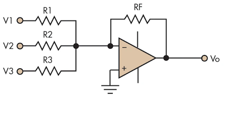 Efficiently Design An Op Amp Summer Circuit Electronic Design
Efficiently Design An Op Amp Summer Circuit Electronic Design
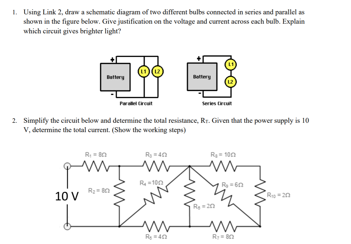 Solved 1 Using Link 2 Draw A Schematic Diagram Of Two D Chegg Com
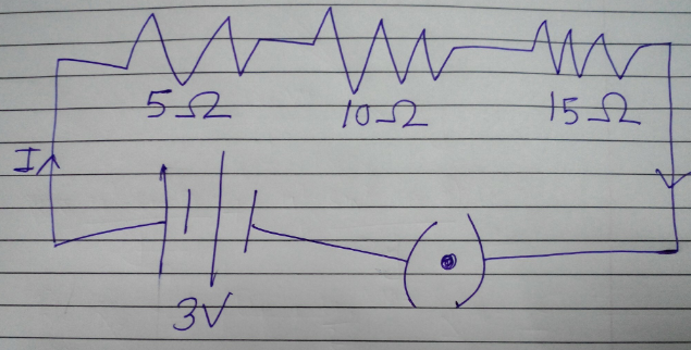
 Draw A Circuit Diagram For The Figure Below Chegg Com
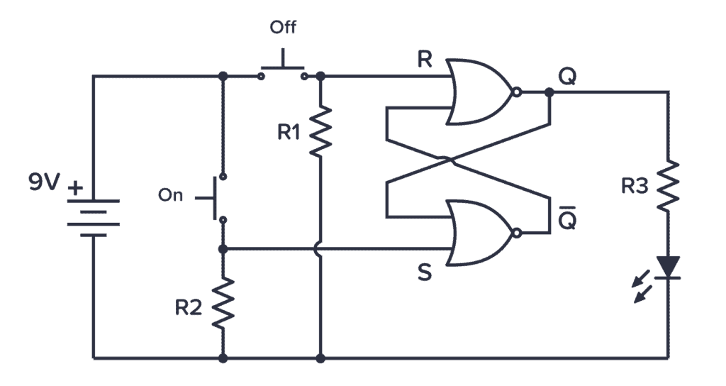 Schematic Symbols The Essential Symbols You Should Know
 Electric Circuit Diagrams Lesson For Kids Video Lesson Transcript Study Com
 21 1 Resistors In Series And Parallel College Physics Openstax
 Solved The Figure Below Shows A Schematic Diagram Of A St Chegg Com
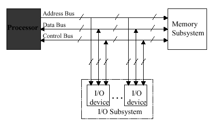 Organization Of Computer Systems Processor Datapath
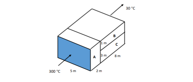 Answered Below Picture Shows The Composite Wall Bartleby
 Electrical Drawings And Schematics Overview
 Draw The Schematic Diagram Given The Figures Below Brainly Ph
 Example 12 8 In The Circuit Diagram Given In Fig 12 10 Suppose The
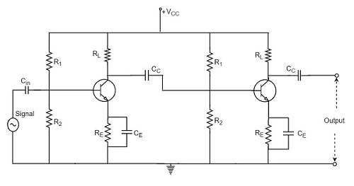 Rc Coupling Amplifier Tutorialspoint
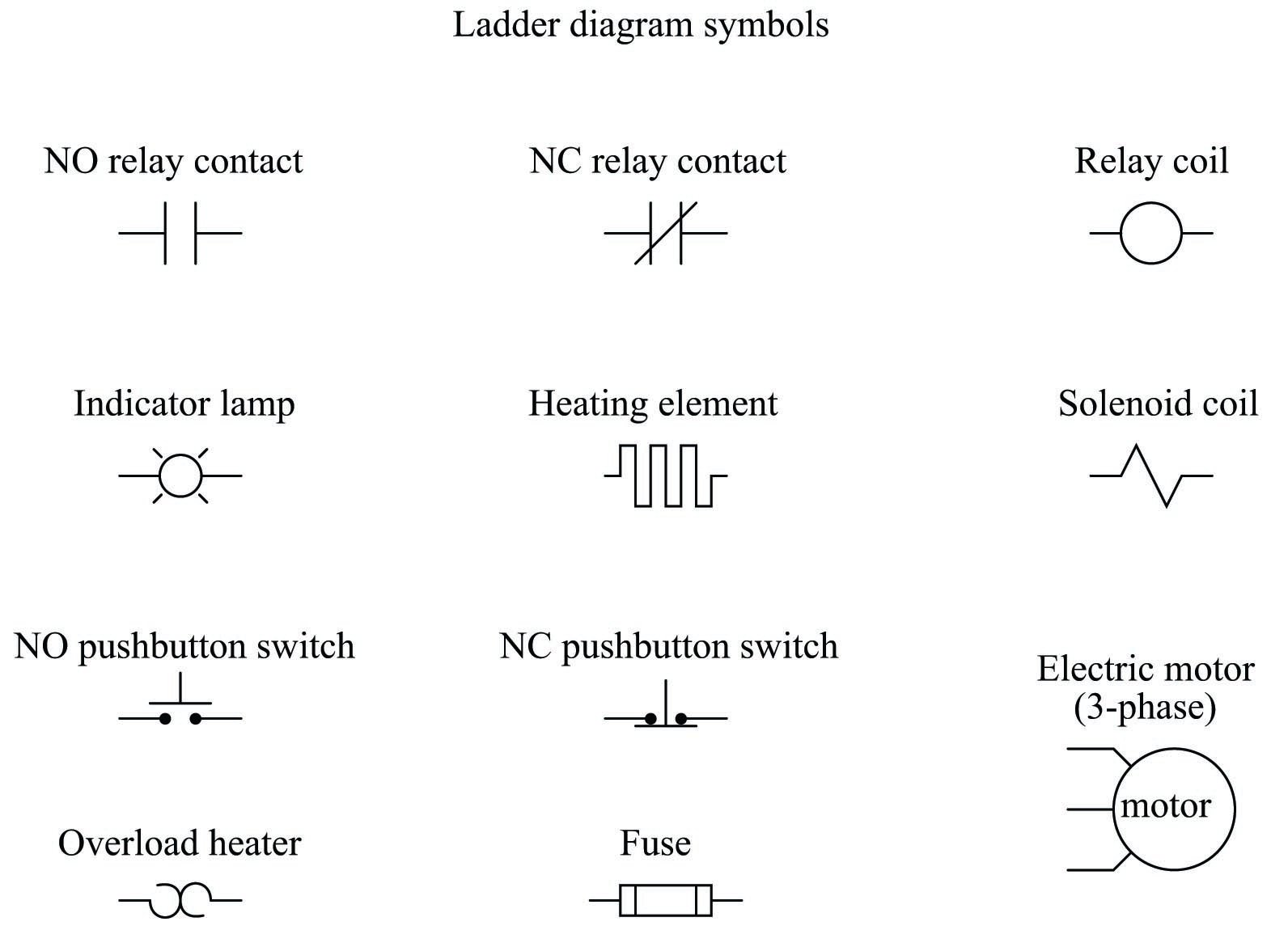 Relay Circuits And Ladder Diagrams Relay Control Systems Automation Textbook
 Parallel Rlc Circuit And Rlc Parallel Circuit Analysis
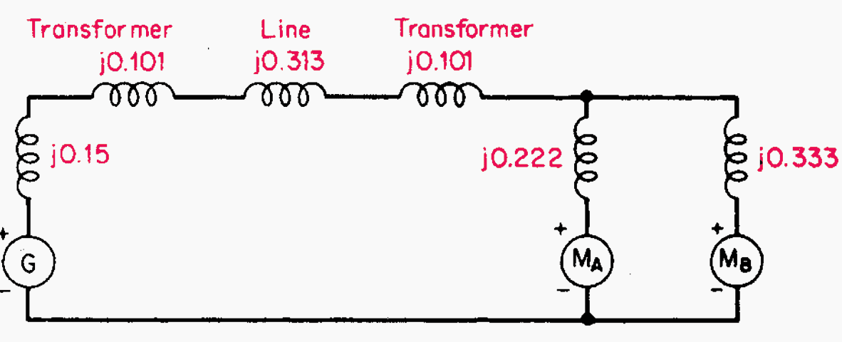 How To Calculate And Draw A Single Line Diagram For The Power System Eep
 Solved 8 82 Figure P8 82 Shows The Schematic Diagram Of A Cogeneration 1 Answer Transtutors
 The Schematic Diagram A Basic Element Of Circuit Design Analog Devices
 Planet Analog When Gnd Isn T Gnd Single Ended Circuits Become Differential
 The Logic Circuit Shown In The Figure Below Is Used To Activate An Alarm When Its Output Y Is Logic High Or 1 Draw A Truth Table For The Circuit Showing The
State Tables And State Diagrams
 10 Simple Online Drawing Tools For Effective Thesis Diagrams Ilovephd
 What Is The Resistance Between A And B In The Figure Given Below Youtube
 Interpreting Piping And Instrumentation Diagrams Symbology Aiche

Comments
Post a Comment